Self-contained units for land well operations, pressure control, and wireline assistance
Home / PMM Landline Winch
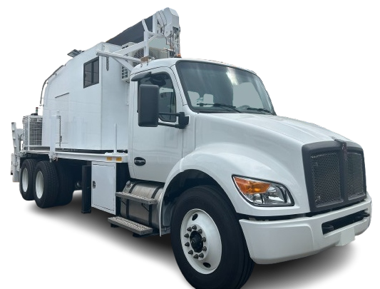
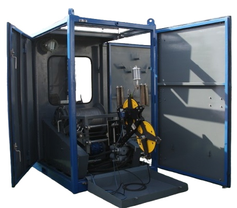
PMM Landline with Auxiliary Crane
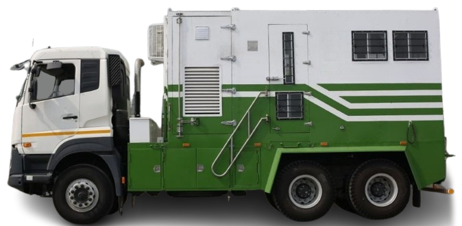
PMM Landline are self-contained units designed for use on land wells. The large amount of storage on these units allows them to transport virtually all pressure control equipment’s like grease injection units, lubricator risers, BOP etc to the well. The Crane can be used an auxiliary crane to assist with wireline jobs in the oil fields, this includes for example the construction and dismantling of the lubricator and the BOP’, a BOP rack and tools rack are mounted on the trailer.
Key features of allPMM Landline FOR LOGGING SERVICES
Hydraulic telescoping sections
Compact transport & setup
Mechanical safety locks
Loading & line pull capacity
Stand-alone or integrated winch
Wind & environmental rating
Safety features
High-strength steel
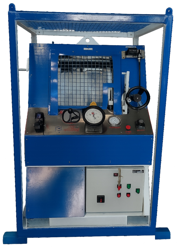
Instrumentation / monitoring
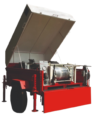
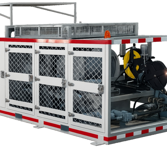
WINCH SYSTEM
Max. Height not more than 4m/13 feet (4000 mm) from ground level.
Length of the Truck: Max. 40 feet (12192 mm).
Max. Width 8.53 feet (2600 mm).
Weight: Sufficient to mount telescopic mast crane (laden & un-laden weights as per CMVR
Truck Drive: 6 X 4, right hand drive, 420 HP
Truck Engine: Diesel engine EURO-6/BS-VI SCR+EGR.
All steel day & night cabin with driver + co-driver seat & air-conditioned with climatic control
Fuel tank: minimum 400 Its capacity, made of steel & chassis mounted, with fuel anti-theft protector system
Gross vehicle weight of the Truck chassis: min. 28000 kg.
Boom capacity: 15 TON to 26 TON, Four to Six section telescopic boom with length upto 127 feet with additional jib and operating angle of maximum 80 deg.
Can work at an height of upto 135 feet.
Mounting: Rear mount 360° stable unit, proportional/Sequence Synchronous boom extension.
High performance planetary winch
Heavy duty efficient hydraulic system with automatic hydraulic oil cooler Rear mounted dual operator controls at appropriate height with clear visibility of boom all around.
Rear and front outrigger for maximum stability while lifting load.
Lock valves in the hydraulic lift cylinders will hold from collapsing / lowering of mast in the event of hydraulic hose failure/burst etc.
Alert systems both audio & visual ATB, LMI, automatic safe load indicator, boom angle indicator, boom length sensor indicator, safety latch for hook block, hoist limit switch system, safety harness
Relief valve will protect the hydraulic system in the event of over-load.
A rear view camera (with DVR, 1 tb) suitably installed to have a clear view of the operational area.
Hydraulic hoses will be high-pressure and temperature rating with adequate safety factor
Weight distribution on front and rear axles will be so as to provide the maximum stability to the vehicle
Drive: 8×4 for Higher GVW-35000 KG which increases the Weight Carrying Capacity & Provides more Stability.
Truck BHP: 250 HP to 460 HP
Lifting capacity: 3 Ton, 5Ton, 8 Ton, 15 Ton, 23 Ton, 26 Ton.